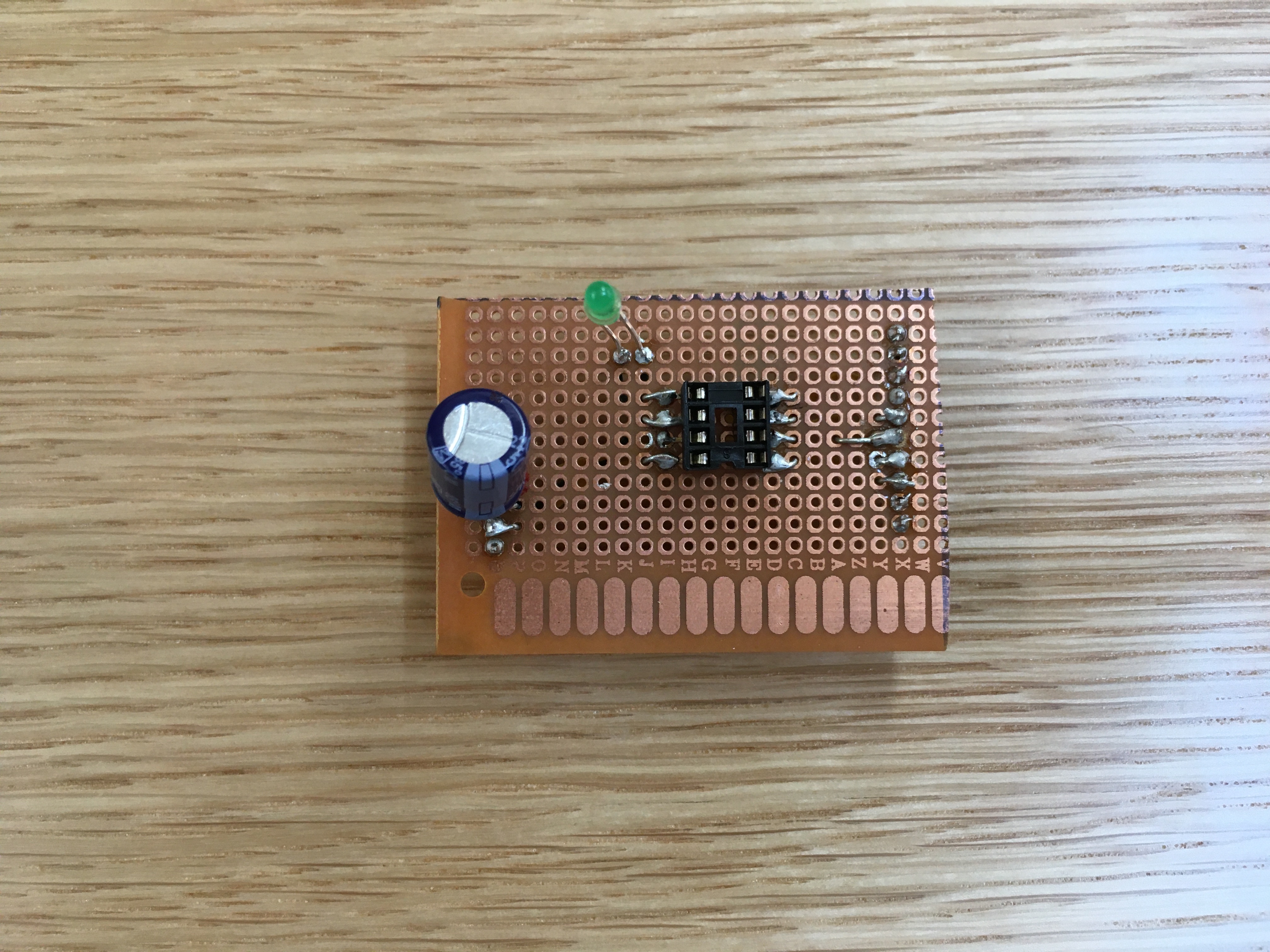
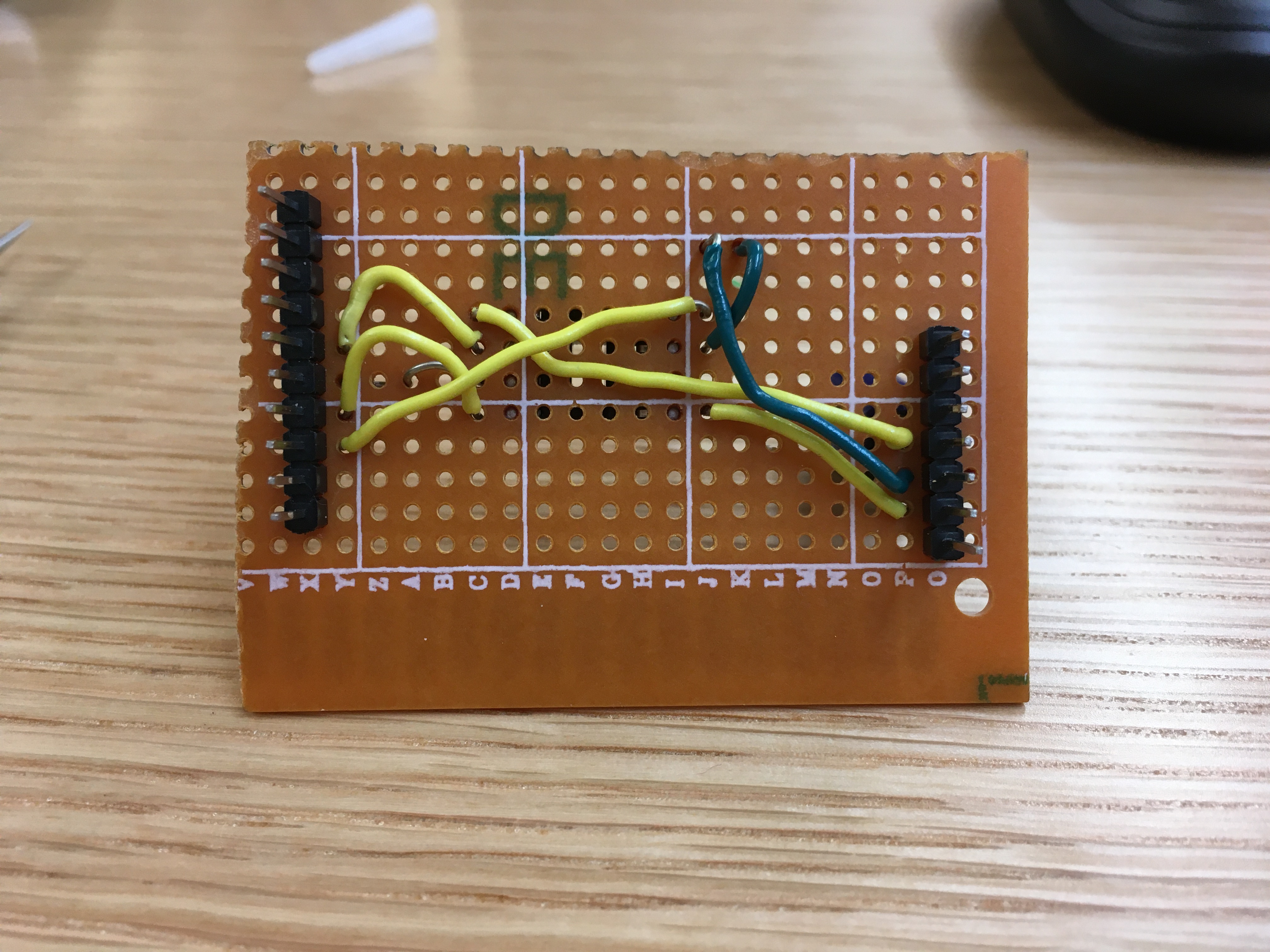
My first part of the assignment involved finishing the ATTiny85 programming jig, since I hadn’t got too far in class—only one pin was soldered. While the process felt somewhat tedious, it went smoothly. I checked for shorts between any two pins using a potentiometer and found none. I followed the programming tutorial on the class website in order to burn the ATTiny’s bootloader and upload my own sketch. Surprisingly, everything worked from the first attempt. I ended up adding an LED to the jig and connecting it to the ATTiny’s digital pin 3, as a way of improving the jig’s functionality to testing, in addition to programming.
For the project application, I decided to use a component I’d never worked with before. During last semester’s garage sale, I purchased a 16x2 LCD screen and never had the chance to use it. I will say from the get go that my attempt failed :). Here is why.
I started by connecting it to my Arduino Nano and making sure it works, since I had never tested it before. It did, and you will have to trust me on this one since I didn’t document it (🤦♂️). But this is the (very simple) code that I used, taken from the LiquidCrystal library’s help.
#include <LiquidCrystal.h>

// initialize the library with the numbers of the interface pins

LiquidCrystal lcd(4, 3, 6, 1, 2, 5);

void setup() {

   // set up the LCD's number of columns and rows:

   lcd.begin(16, 2);

   // Print a message to the LCD.

   lcd.print("hello, world!");

}

void loop() {

   // set the cursor to column 0, line 1

   // (note: line 1 is the second row, since counting begins with 0):

   lcd.setCursor(0, 1);

   // print the number of seconds since reset:

   lcd.print(millis() / 1000);

}
Very briefly, the LCD screen has 16 pins. 8 of them (D0 to D7) are used for sending over bytes of information that need to be displayed on the screen, as well as commands (move cursor, clear screen etc.). Two of them are power and ground (VSS, VDD). Two of them are power and ground for the backlight LED (A and K.) Three of them are used in order to set different communication modes for the 8 data pins (RS, RW and E). And last, but not least, one pin (V0) needs to be hooked to a potentiometer and it controls the screen’s contrast.
16 is a lot of pins, since our ATTiny only has 8 pins total, 5* of which can be used for data. (potentially 6 if we consider the RESET pin, more on that in a bit.) The good news is that we can operate the LCD screen by using only 6 pins: RS and E for setting the communication modes, and 4 of the 8 data pins. The LiquidCrystal library implements an 8-bit mode and a 4-bit mode, meaning that the same information can be sent to the screen using only pins D4 through D7. The bad news is that the ATTiny85 only has 5 digital pins available by default.
After some googling, I found out that it is possible to use the RESET pin as a digital pin, and that there are two ways of doing that:
1) By changing the fuse bits on the ATTiny in order to disable the RESET function on digital pin 5 and then performing a fuse reset in order to re-enable programming the chip if necessary
or
2) By doing some circuitry black magic in order to use digital pin 5 while consistenly keeping it under the reset voltage.
I straight up did not understand the black magic in #2. I did some more digging around #1 and also found the Fuse Calculator, but stopped since I didn’t quite know how to run avrdude outside of the Arduino IDE and I didn’t want to risk bricking the ATTiny. But those are just excuses, it seems doable.
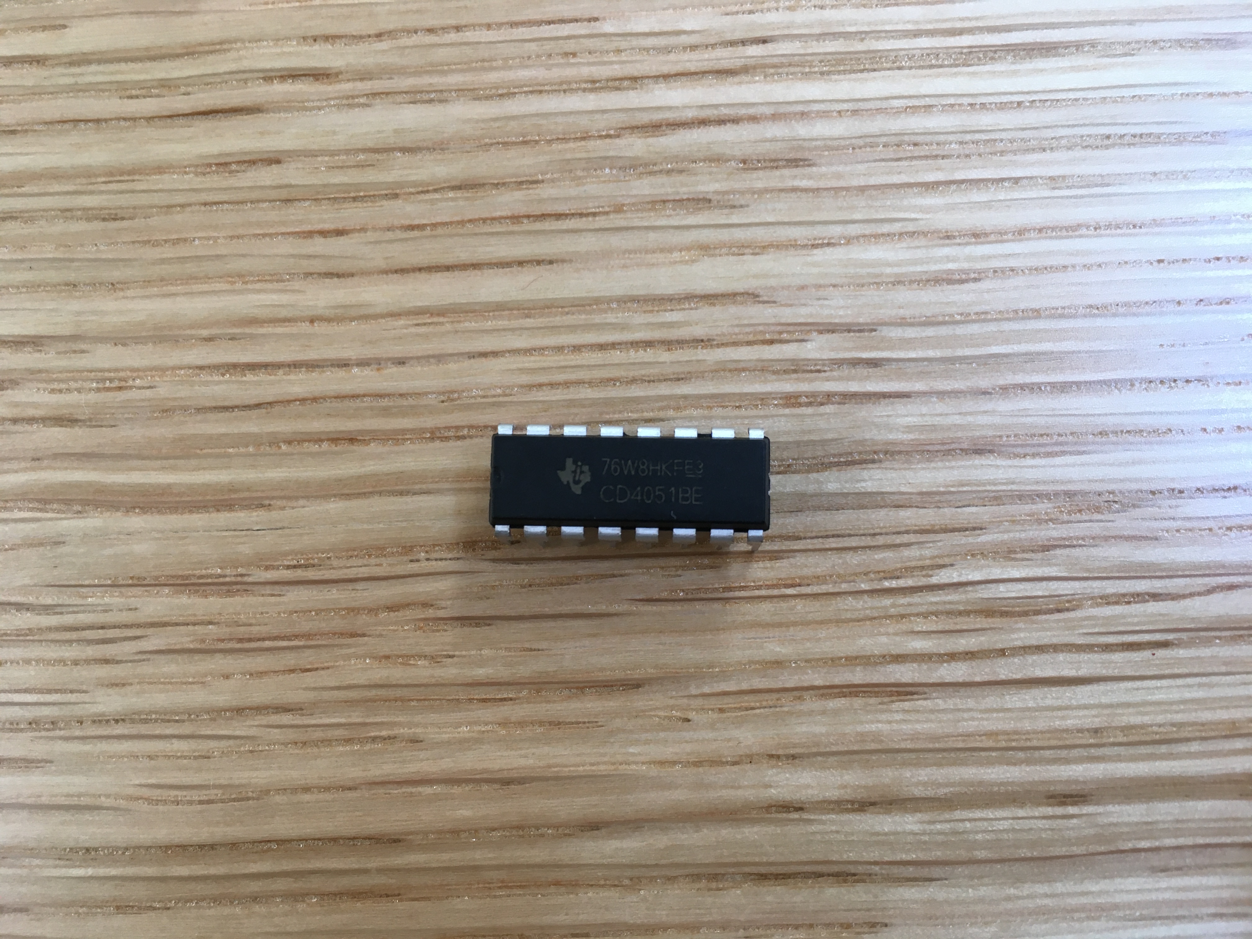
The third option that arose on the horizon was using a multiplexer. I found one in the yellow bins (CD4051BE) and checked out the tutorial for how to use it with Arduino. I understand it conceptually, but using it would require making some manual changes to the LiquidCrystal library. While I’m generally down to do that, it seemed too tedious of a pursuit for this assignment.
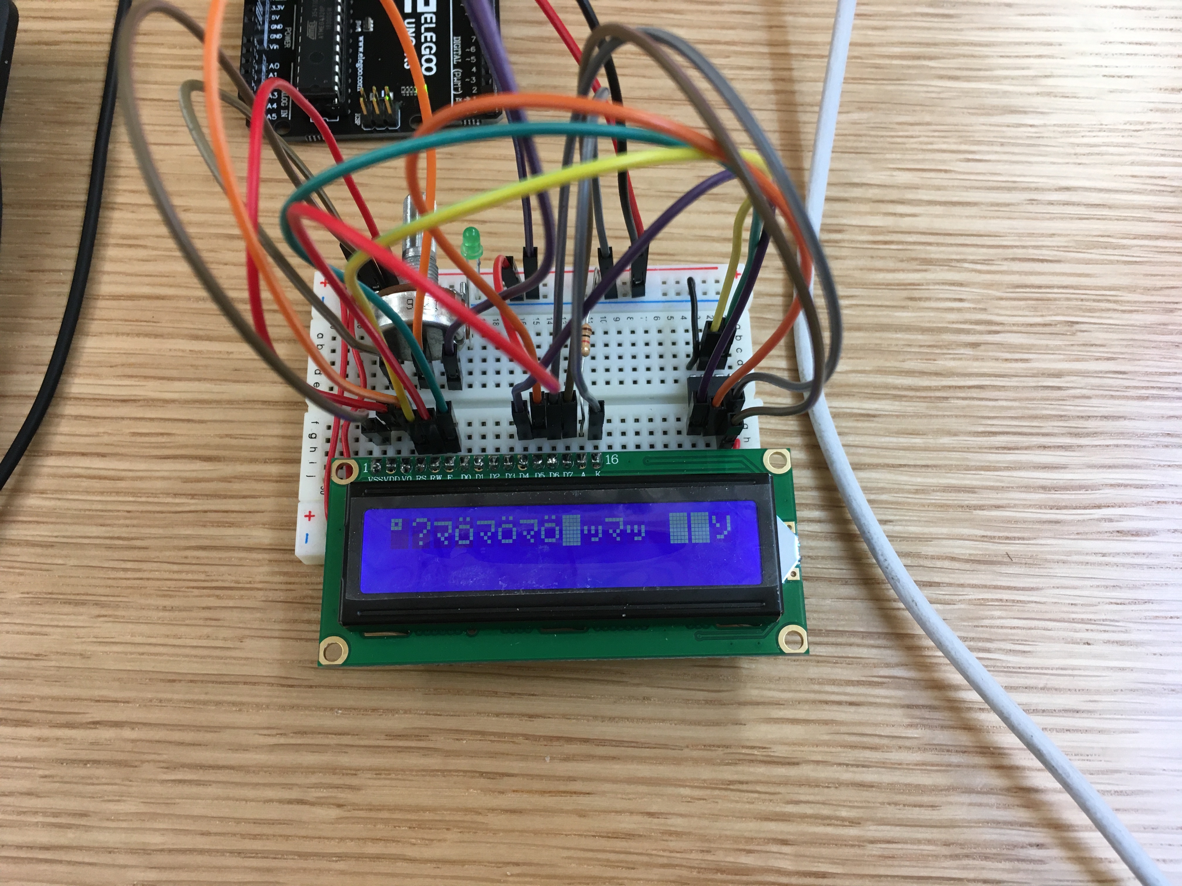
The result of this exercise is that the LED screen works, but displays gibberish, since I had to sacrifice one of the 4 data pins. I ended up plugging it into power, so it’s consistently on HIGH.