This week’s physical computing labs involved working with analog input and output for the Arduino, as well as soldering. Since we’re having a review week, I chose to focus on two things: 1) Improving the LED sequencer I built for the previous lab; and 2) Getting outside of the breadboard and working with resin, a material I’ve wanted to experiment with for some time.
Sequencer 2.0
To recap, last week the sequencer used 3 steps—3 LEDs, each blinking when the current step is playing a note, and 3 potentiometers, used to adjust the frequency of the note played at each step. It also included a 4th potentiometer which controlled the perceived “speed” of the sequencer—how much time is spent playing the note at each step. This week’s improvements included:
-
soldering the speaker connecting wires, which were previously attached to the speaker using alligator clips;
-
adding a 4th step to the sequencer, in order to play slightly more complex sequences; ideally, we would have 8 or 16 steps, but real estate is limited on the breadboard;
-
adding another control input to the sequencer in the form of a photoresistor; this allows for controlling the overall pitch of the played sequence by covering or uncovering the sensor with one’s hand;
-
improving the software such that the Arduino
loopcycle is not dependent on the speed of the sequencer anymore; this means that frequency of a step’s sound can now be adjusted while the step is playing; -
experimenting with different sensitivity levels for the photoresistor reading (I ended up settling on dividing the output into 8 different buckets, since the sensor readings were quite noisy.)
Here is the photoresistor in action:
While I was initially going for the theremin continous bending sound quality, I realized that was going to be difficult for two main reasons: the noise in the photoresistor reading (even when averaged over time) and the loop function timing trade-offs between tone working properly and proper responsivity. So I went a different direction and started working with only discrete quantities. As mentioned before, I divided the photoresistor output into only roughly 8 different buckets. In terms of the frequencies that get played by the sequencer, they all full octaves apart and have the C pitch (the step frequencies get rounded to multiples of 65.) This produces an effect similar to a quantizer.
Here are two more videos of playing the sequencer. The noise in the photoresistor changes the pitch here and there, which adds an improvisation quality to the sound. I find this enjoyable.
LED Resin Cube
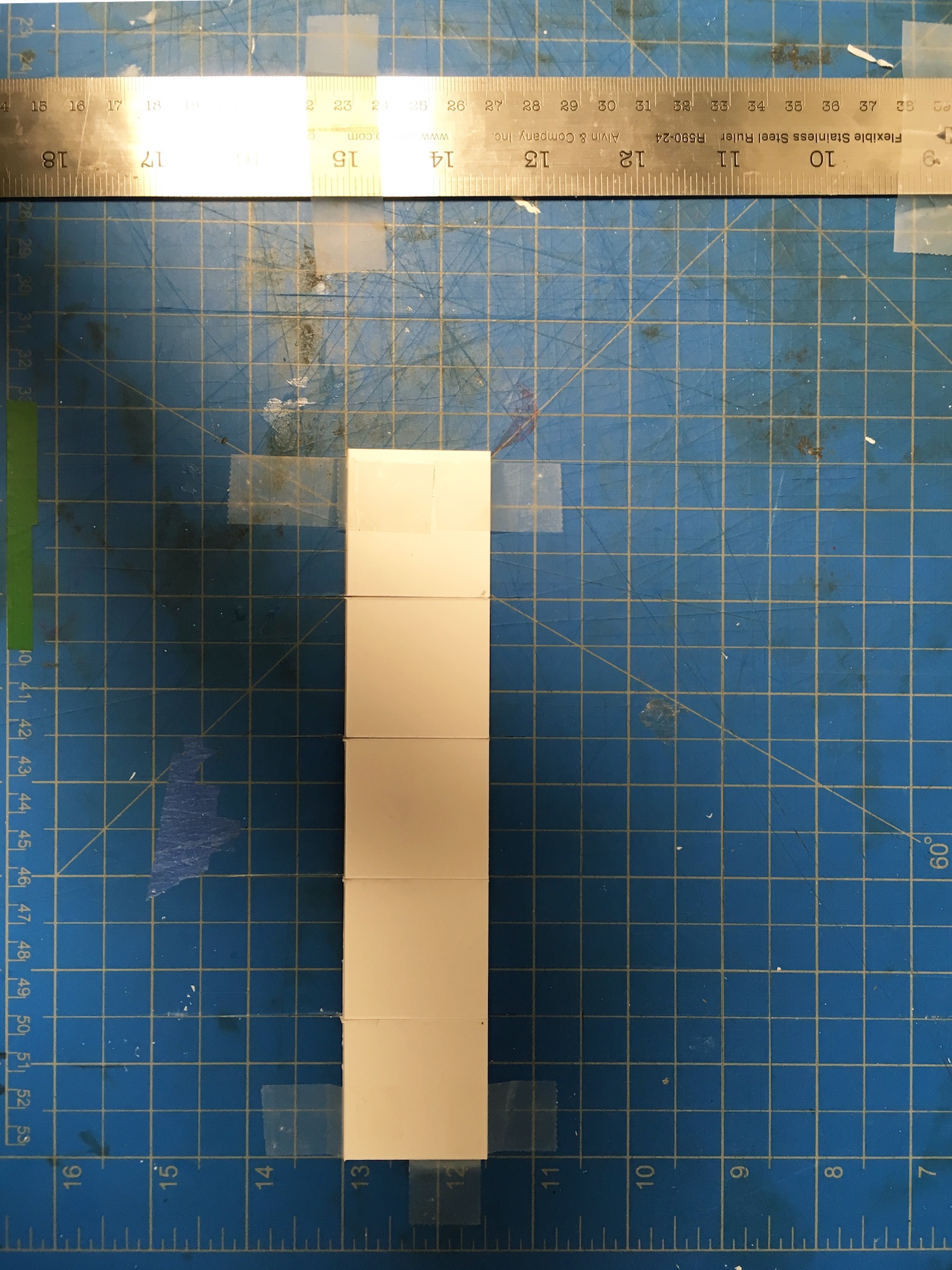
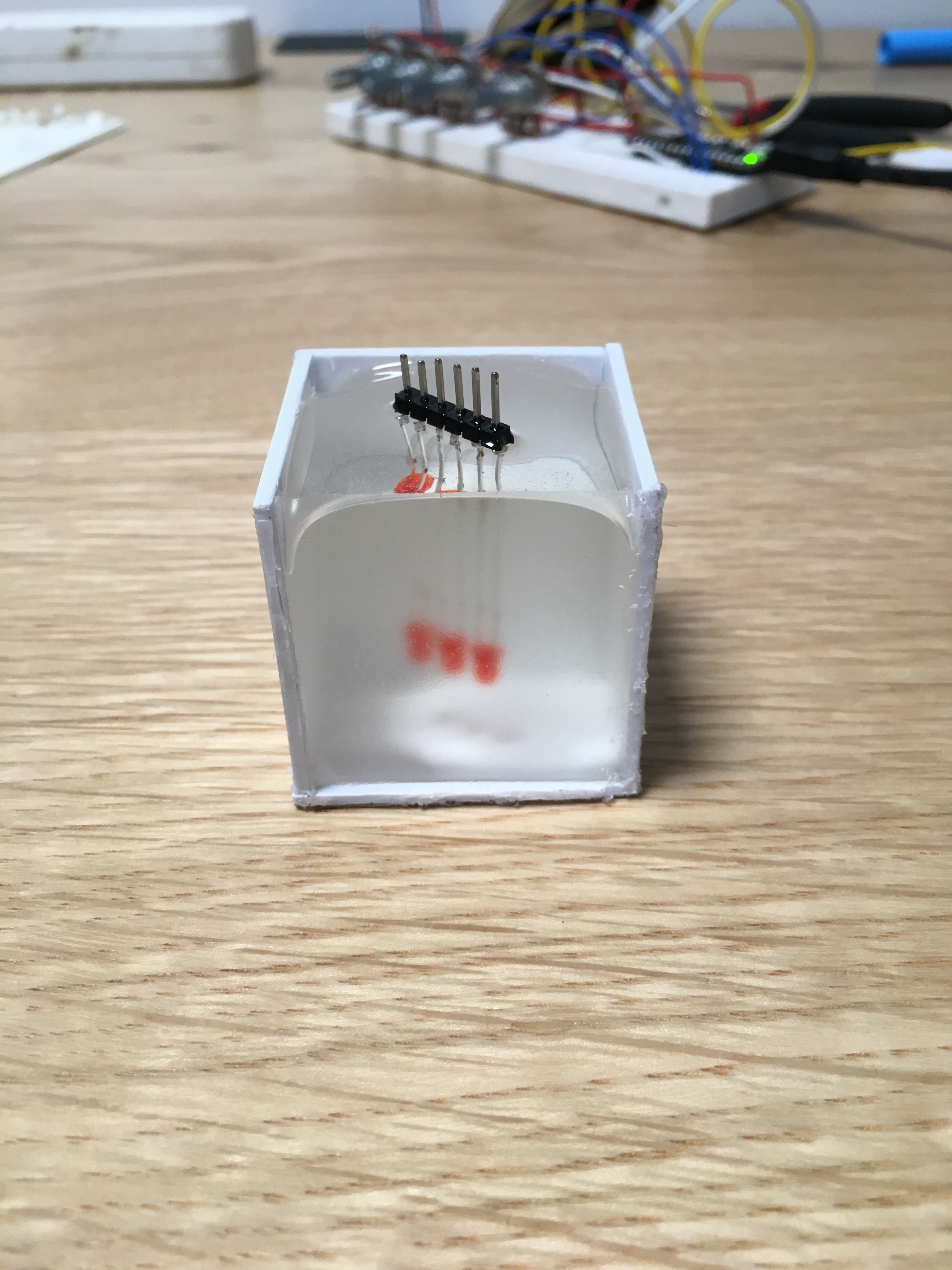
This project came about out of a desire to use materials outside of the breadboard and practice soldering at the same time. I’ve been wanting to experiment with resin for some time, so I decided to build a small resin light. After purchasing supplies from Blick, I built a cube mold for the resin, using a 1/8in thick plastic sheet.
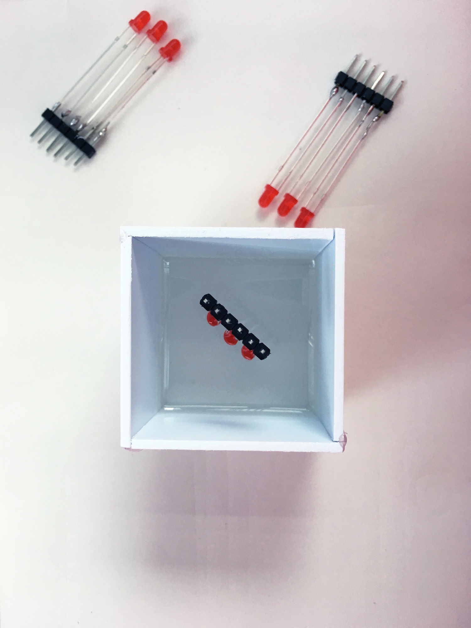
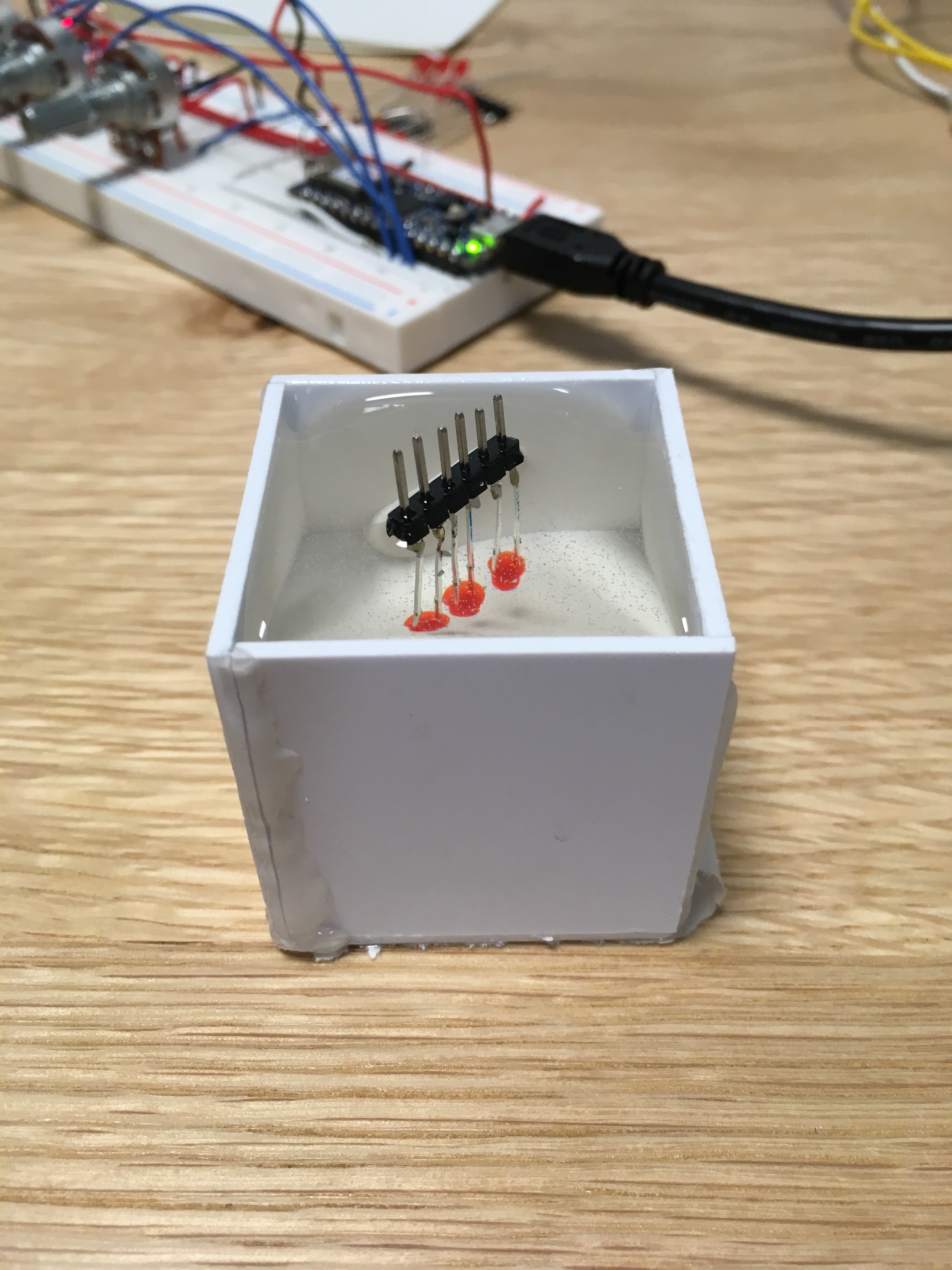
I got the 5 cube sides together using a glue gun, and poured the first layer of resin—about 0.75in thick. After letting it cure for about 8 hours, I added the 3 red LEDs and poured the second and last resin layer.
After letting the second layer cure overnight, the cube was ready to come out of its mold. I noticed that the top corners of the cube were not even with the rest of the surface. This might have to do with the resin curing process emanating heat, which might have interfered with the glue on the sides of my square.
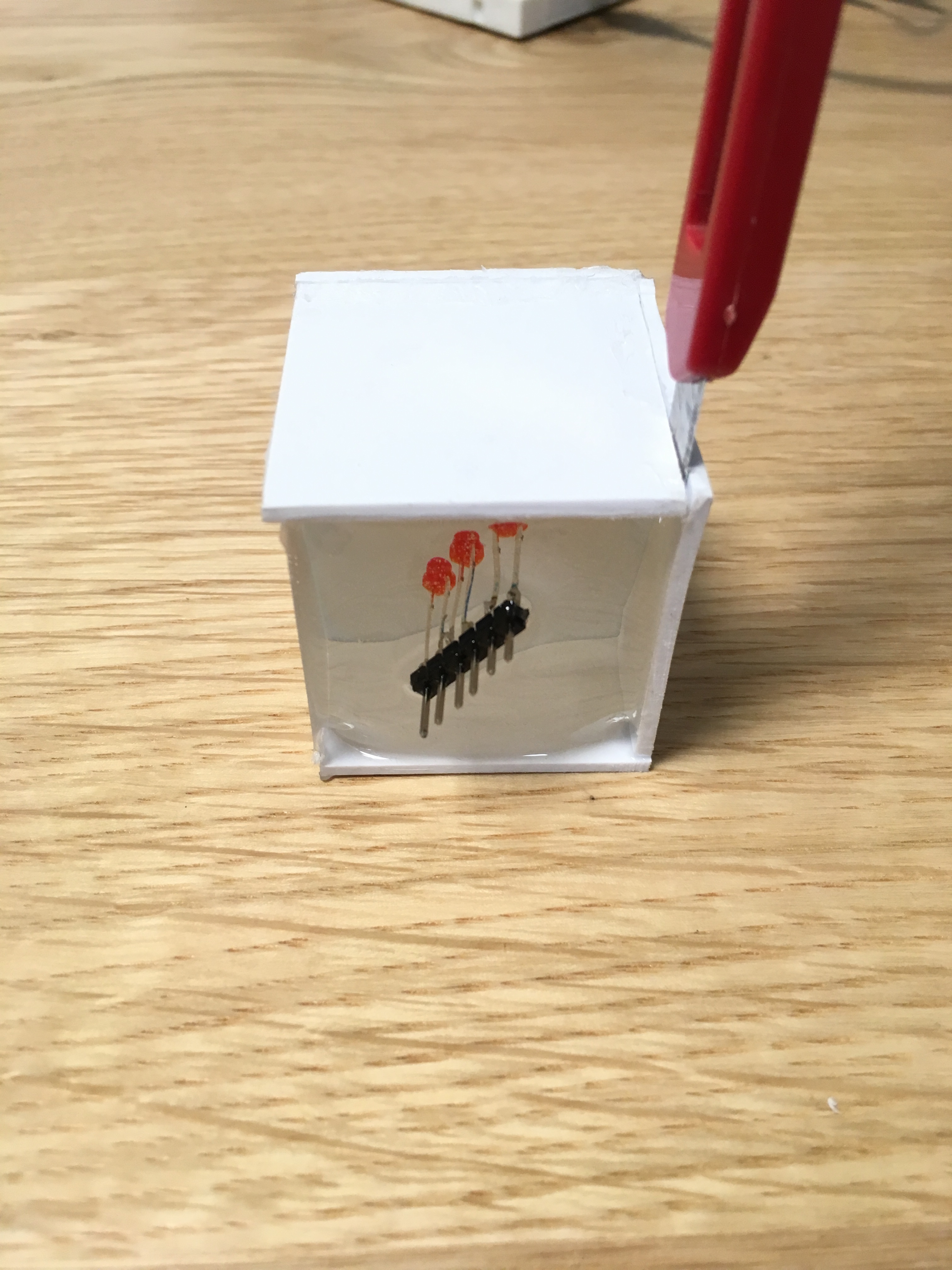
After removing all edges of the plastic mold, the resin cube looked like this:
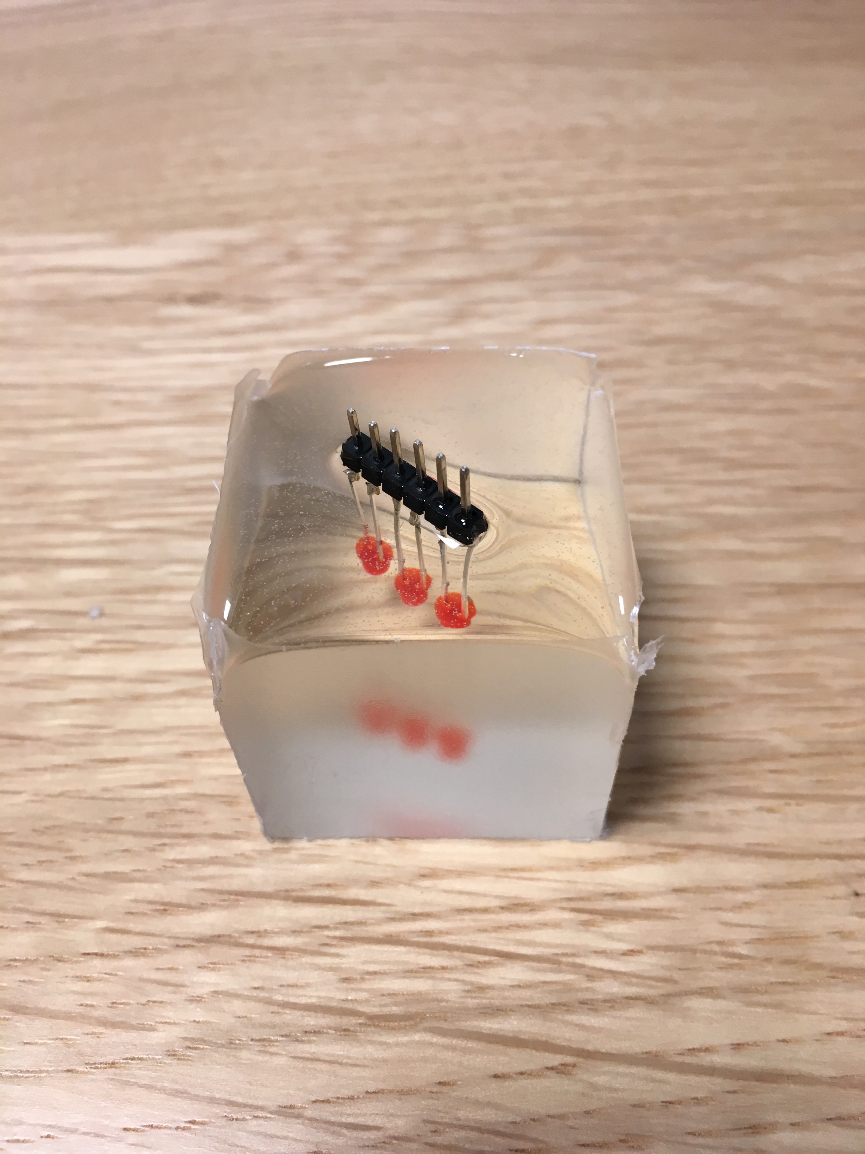
You can notice that the side which was exposed to air is fully transparent, while the sides that were enclosed by plastic have a layer of translucent material. After sanding the cube in order to get rid of the material excess at the edges and get a uniform look, I attacned six pins to the bottom and soldered together the even ones and the odd ones, as a way of having a single power source for the 3 LEDs. (in the ugliest soldering job the planet has seen.)
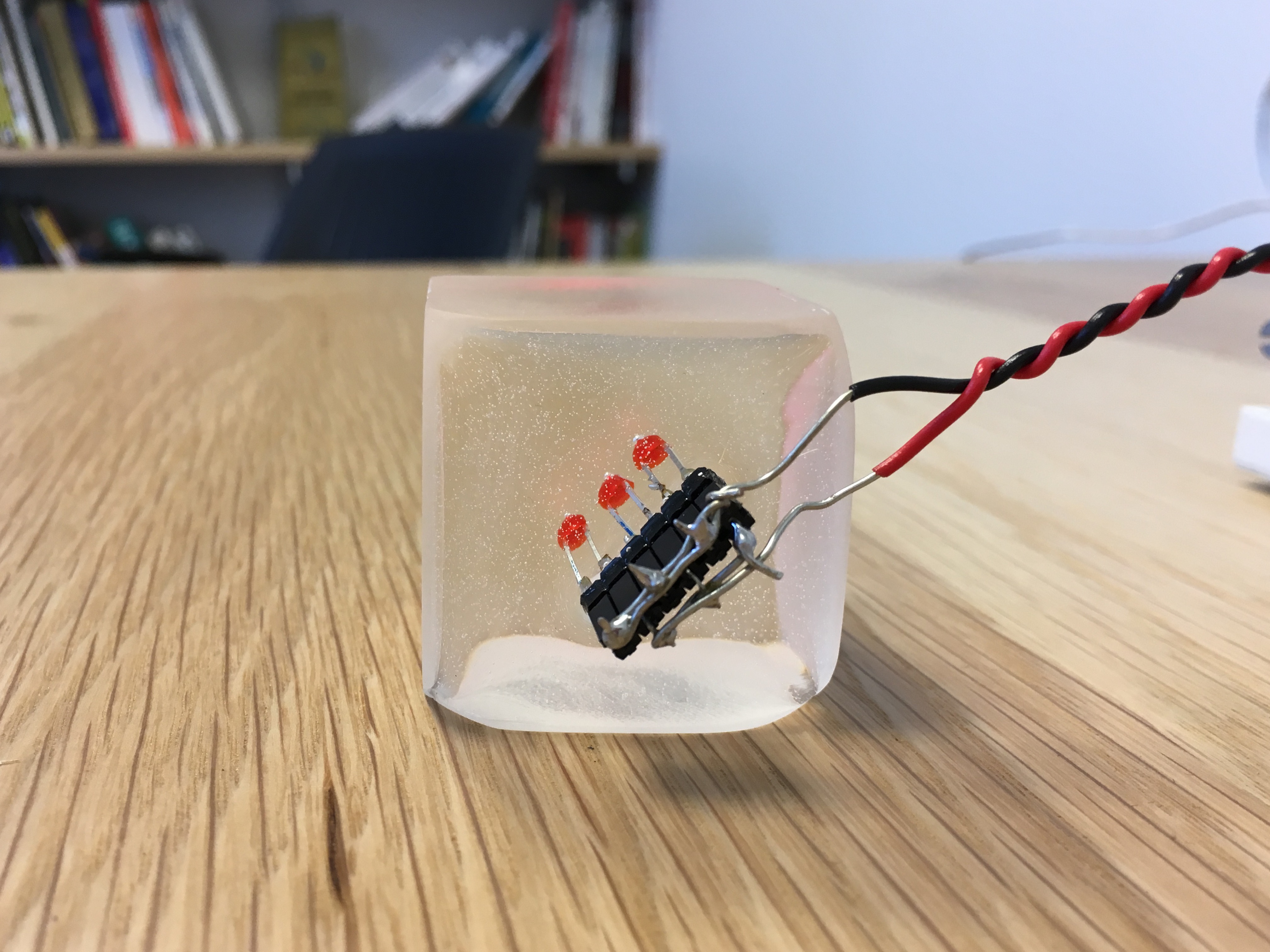
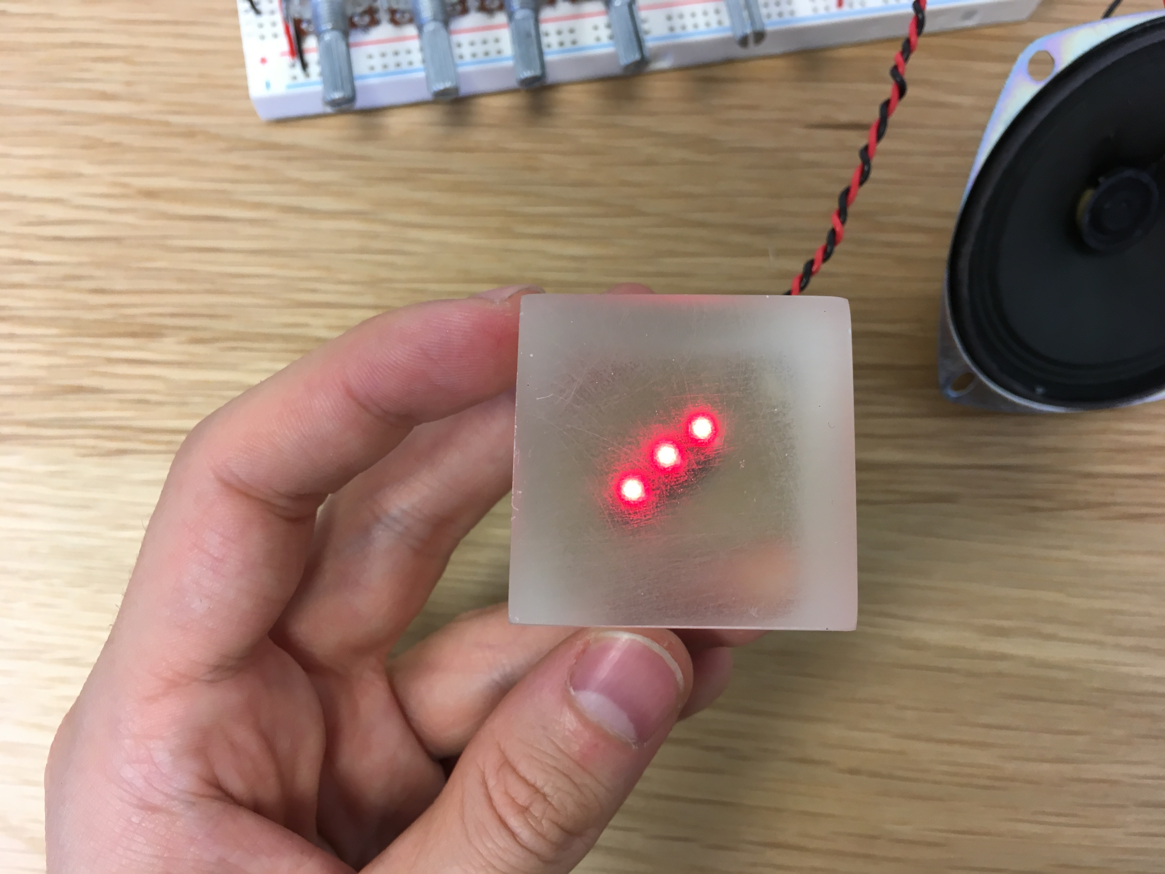
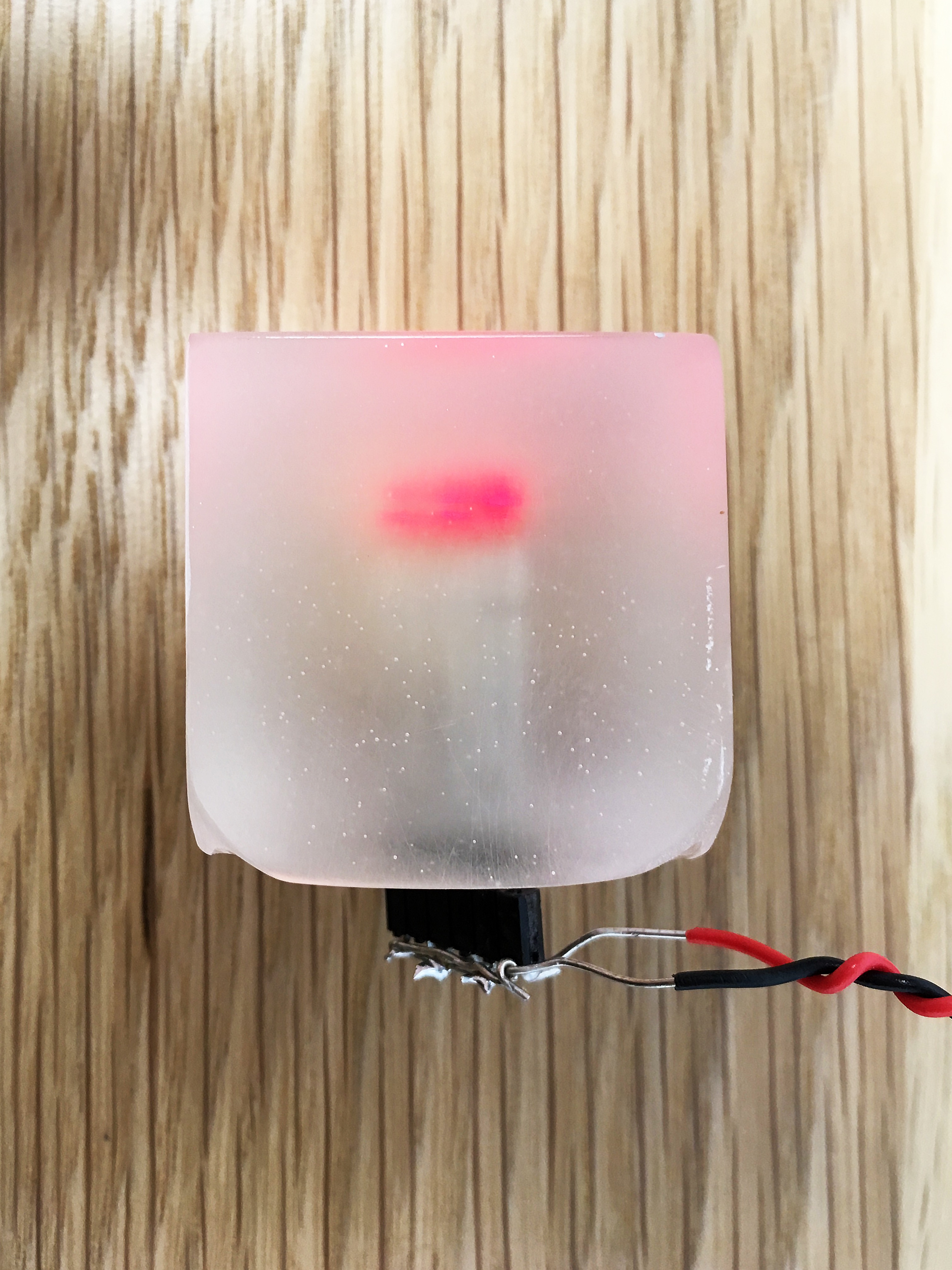
After plugging in the cube, the LEDs (surprisingly?) lit up. The second failure of this project consisted in the fact that I was expecting the light to be way more diffuse, but instead the 3 LEDs are clear. This is due to the fact that most of the cube’s inner volume is fully transparent, so the problem could be solved by adding a small amount of white or silver paint in the mix.
I will likely work with resin again, but next time I will choose a different material for the mold. Using plastic made the mold unusable after getting the resin out of it. 3d printing the positive shape, creating a silicone mold and pouring resin into that sounds like the right choice of materials and process for pretty much any (small scale) shape. To be continued.
For reference, the sequencer code is here:
int ANALOG_POT_1 = 3;
int ANALOG_POT_2 = 2;
int ANALOG_POT_3 = 1;
int ANALOG_POT_4 = 4;

int ANALOG_POTS[4] = {ANALOG_POT_1, ANALOG_POT_2, ANALOG_POT_3, ANALOG_POT_4};

int ANALOG_PHOTO_T = 0;

int ANALOG_POT_PACE = 6;

int DIGITAL_LED_1 = 9;
int DIGITAL_LED_2 = 8;
int DIGITAL_LED_3 = 7;
int DIGITAL_LED_4 = 4;


int LEDs[4] = {DIGITAL_LED_1, DIGITAL_LED_2, DIGITAL_LED_3, DIGITAL_LED_4};

int DIGITAL_SPEAKER = 6;


int CELL_DELAY = 100;

int potValues[10], frequencies[10];

int NO_CELLS = 4;
int currentCell = 0;

int currentTime = 0;
int TIME_RESOLUTION = 150;

// int BIG_LOOP = 0;
// int BIG_LOOP_CNT = 1;

void setup() {
  // put your setup code here, to run once:
  Serial.begin(9600);
  pinMode(DIGITAL_LED_1, OUTPUT);
  pinMode(DIGITAL_LED_2, OUTPUT);
  pinMode(DIGITAL_LED_3, OUTPUT);
  pinMode(DIGITAL_LED_4, OUTPUT);
}

void loop() {
  int pacePotValue = analogRead(ANALOG_POT_PACE);
  if (pacePotValue < 768) {
    CELL_DELAY = map(pacePotValue, 0, 768, 50, 1000);
  } else {
    CELL_DELAY = map(pacePotValue, 768, 1024, 1000, 8000);
  }

  int lsv = analogRead(ANALOG_PHOTO_T);
  float lightSensorValue = lsv - lsv % 150;
  float thereminFactor = thereminFactor * 0.5 + (lightSensorValue / 1024.0 * 4.0 + 0.66) * 0.5;

  for (int i = 0; i < NO_CELLS; i++) {
    potValues[i] = analogRead(ANALOG_POTS[i]);
    frequencies[i] = map(potValues[i], 0, 1024, 132, 600) * thereminFactor;
    frequencies[i] = frequencies[i] > 65 ? (frequencies[i] - frequencies[i] % 65) : frequencies[i];
    if (potValues[i] < 32) frequencies[i] = 0;
  }

  if (currentTime > CELL_DELAY) {
    currentTime = 0;
    digitalWrite(LEDs[currentCell], LOW);
    currentCell = (currentCell + 1) % NO_CELLS;
  }

  if (frequencies[currentCell] > 0) {
    tone(DIGITAL_SPEAKER, frequencies[currentCell]);
    digitalWrite(LEDs[currentCell], HIGH);
    delay(2);
  } else {
    noTone(DIGITAL_SPEAKER);
  }

  delay(TIME_RESOLUTION);

  currentTime += TIME_RESOLUTION;

//  BIG_LOOP = (BIG_LOOP + 1) % BIG_LOOP_CNT;
//  BIG_LOOP_CNT += (int)sin(millis());

  Serial.println(lightSensorValue);
  Serial.println(thereminFactor);
  Serial.println("");
}