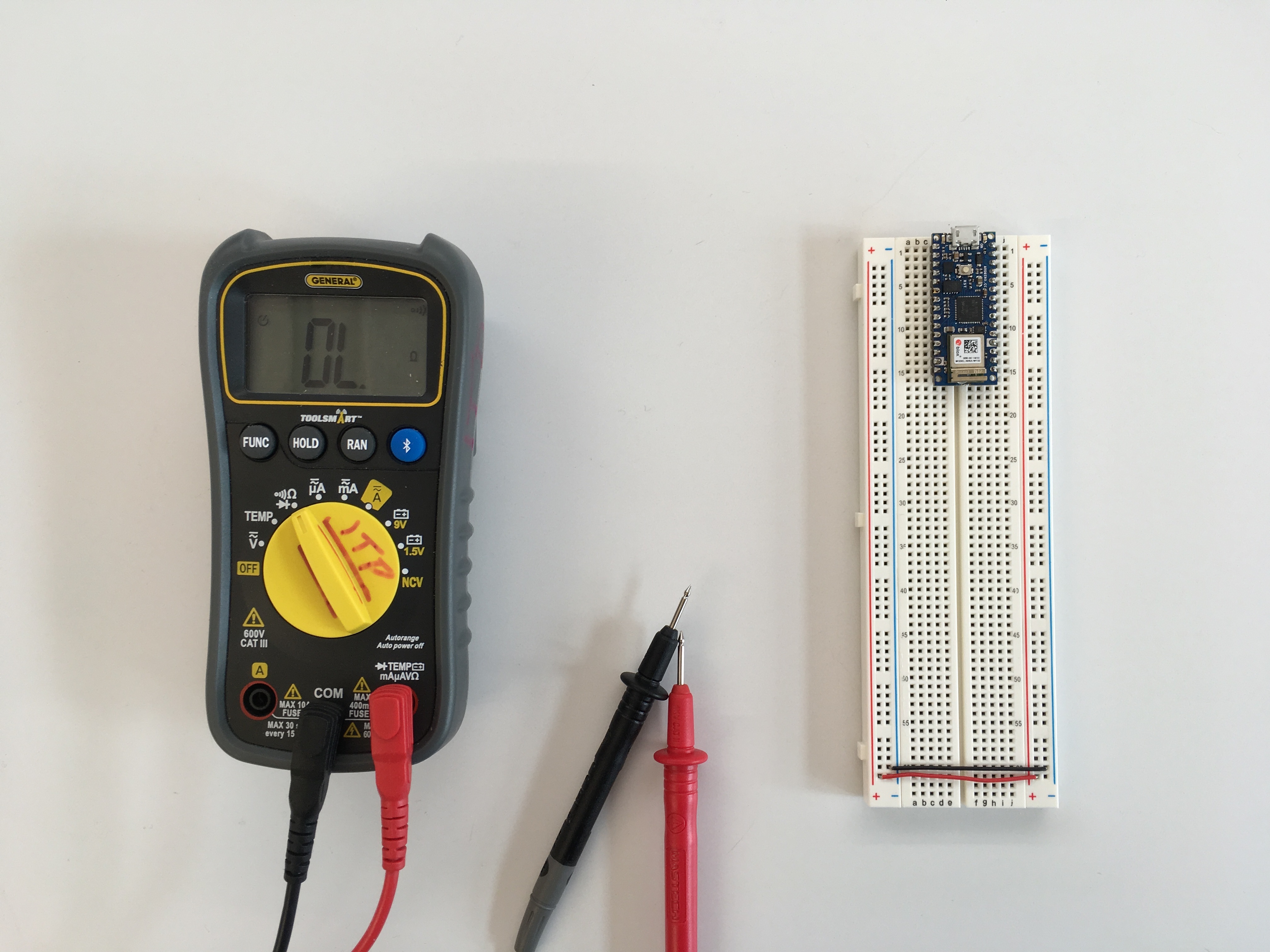
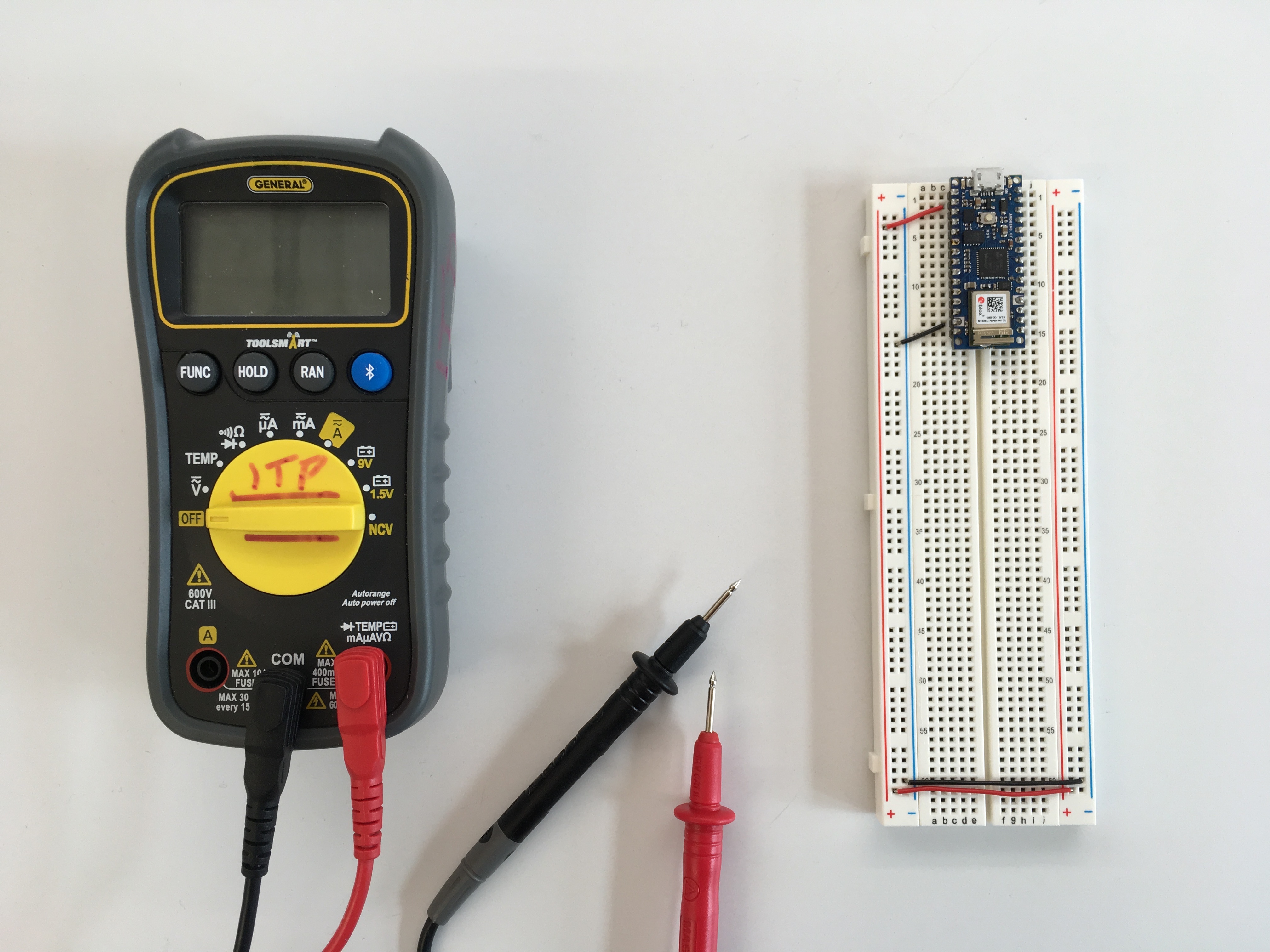
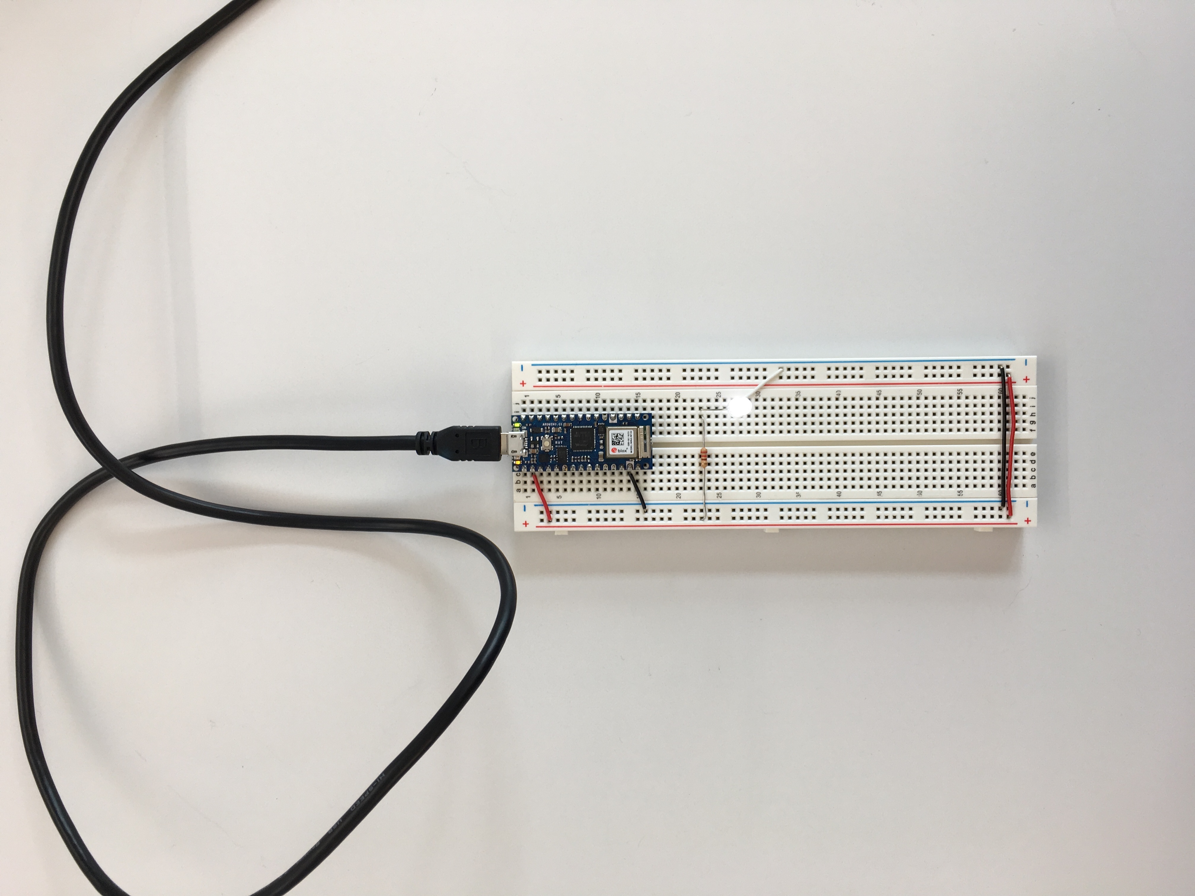
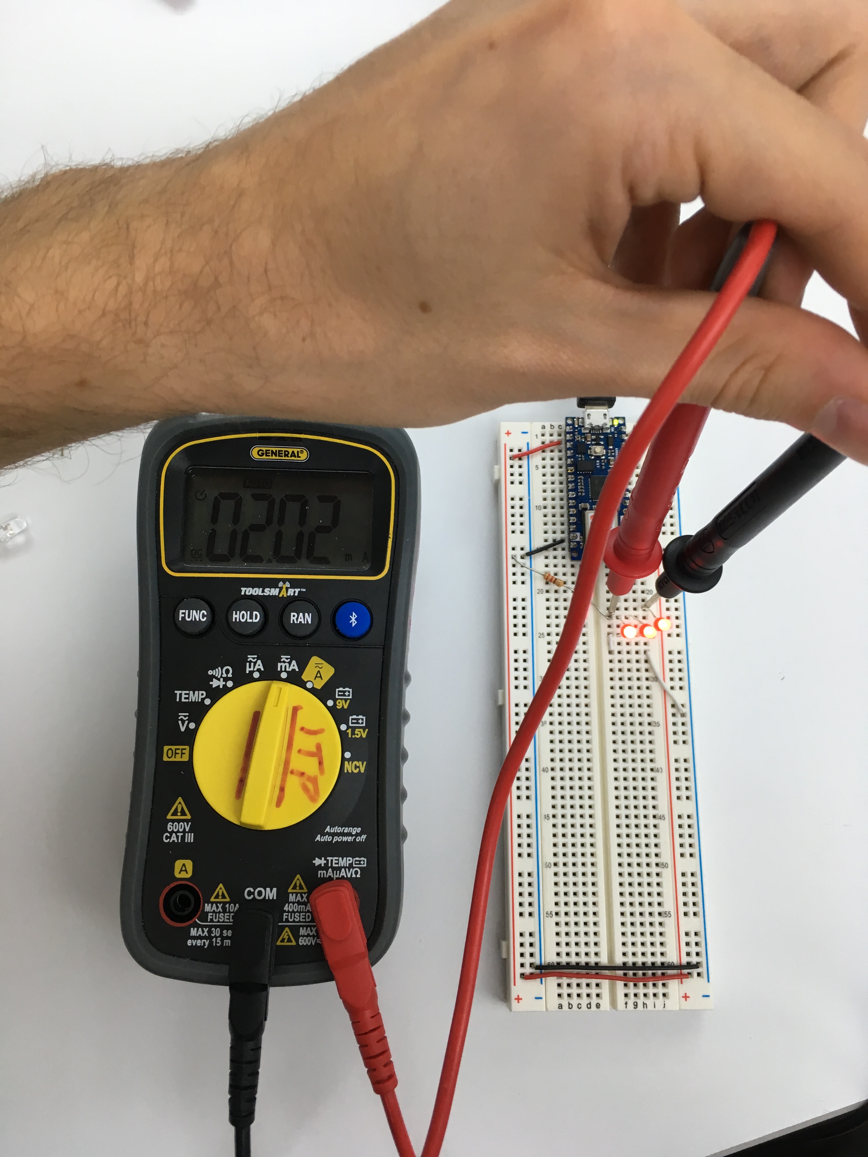
For our first physical computing lab, we were tasked with understanding and experimenting with basic circuit components, working on a solderless breadboard. This involved learning how to use a multimeter—for checking continuity or measuring resistance, voltage, and amperage—as well as creating a few basic circuits, involving a power supply, resistors and LEDs.
As a next step, we introduced a switch into the circuit, while also playing with more LEDs, in series or in parallel.
We also introduced a potentiometer into the setup, as a way to manually adjust the resistance of the circuit and the voltage that gets to our LEDs.
The last part of the assignment involved building a creative switch for our LEDs—one that is not neccesarily a push button, or an existing interface. I was interested in having the LEDs light up when a sound (or rather noise) event is happening, so I came up with this silly contraption. It uses conductive thread to attach the moving piece to the tilted metal rod.